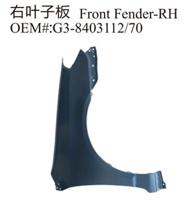
Selection principle of stamping die for automobile stamping parts:
1. First of all, consider the die set under "select stamping die". For the set square die, analyze whether the straight line to be stamped is greater than or equal to 1.5 times of the side length of the die. When stamping the inner side of the circular die curve, analyze whether the arc diameter to be stamped is greater than the die diameter. If so, use the set die.
2. For the contour that can be classified into the basic figure, first search the die library for whether there is a stamping die that is completely consistent with the contour and can punch out the contour with a stamping action. If there is such a die, the stamping die set under "select stamping die" will be ignored and the found stamping die will be used directly.

3. For the rectangular contour, when the long side is greater than or equal to 1.5 times of the short side, it will automatically search whether there is a square stamping die consistent with the short side of the rectangle: for the long circular groove or circular groove, it will search whether there is a circular stamping die with the same groove width. If there is, it will be used directly. If the die is not determined after the above two steps, it will be considered to use the square die or circular die to punch a straight line or arc step by step.
4. If the set die is not suitable, the system will search for the square or circular die from small to large in the stamping die library, and the straight line to be stamped shall be greater than or equal to 1.5 times of the side length of the die.
The description of slip line method shows that only stamping parts with relatively simple shape can establish the corresponding slip line field. And only under very simple boundary conditions can the mathematical expression of slip line be given from the solution of characteristic square. In general, the approximate slip line field needs to be obtained by using the numerical integration of the characteristic equation and recursion point by point according to the given boundary conditions. This method is based on transforming the characteristic line differential equation into a finite difference relationship and using the characteristics of the slip line. Therefore, the slip line method is difficult to be popularized and applied in practical production because of its complex mathematical operation.
Geometric mapping method. They believe that the mapping from workpiece to blank can be realized according to some assumptions without considering the boundary conditions such as deformation force, stress-strain relationship and boundary friction. Firstly, the wooden model is meshed, and the position coordinates of nodes are obtained by coordinate measuring instrument. Or the CAD model can be directly meshed in the computer. Assuming that the thickness of the workpiece remains unchanged during the forming process and the area of the grid before and after deformation is constant, the three-dimensional space grid is mapped to the two-dimensional plane, so that the initial blank shape and the stress distribution of the workpiece can be deduced.
Copyright By © Jiangsu Halreal Vehicle Industry Co., Ltd. Powered by Yicheng Network